Interferometry
Interferometry is the process of making measurements by allowing sound, light, or other kinds of waves to interfere with each other. Interferometry is used for a large variety of purposes, such as studying the velocity of sound in a fluid, locating the position and properties of objects in space, determining the size and properties of objects without actually touching or otherwise disturbing them, and visualizing processes such as crystal growth, combustion (burning), diffusion (spreading), and shock wave motion.
Principle of the interferometer
The interferometer was invented by German American physicist Albert A. Michelson (1852–1931) around 1881. The major features of Michelson's instrument are shown in Figure 1. Light from the source enters the interferometer along one arm and strikes a half-mirrored glass called a beam splitter. The light is split into two equal parts at the beam splitter. The first half reflects off the beam splitter and travels to mirror #1. The second half passes through the beam splitter to mirror #2.
The first beam of light reflects off mirror #1, passes back through the beam splitter, and continues to the detector. Meanwhile, the second beam reflects off mirror #2, returns to the beam splitter, and is also reflected to the detector.
What happens at the detector depends on the paths taken by the two beams. If they have both traveled exactly the same length, they will interfere with each other constructively. But if the distance taken by the two beams is different, an interference pattern will be formed. The kind of pattern produced, then, depends on the difference between the paths taken by the two beams of light.
Words to Know
Beam splitter: A sheet of glass or plastic specially coated to reflect part of a beam of light and transmit the remainder.
Interference: The interaction of two or more waves.
Velocity: The rate at which the position of an object changes with time, including both the speed and the direction.

Variations on the Michelson interferometer
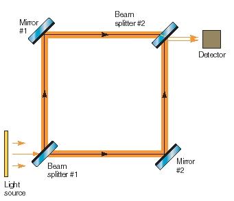
In the hundred years since Michelson invented the interferometer, scientists have devised a number of variations on the original instrument. Most of these variations were designed to make special kinds of measurements. One example is the interferometer invented in 1891 by L. Mach and L. Zehnder. A top view of this instrument is shown in Figure 2.
Light leaves the source and is divided into two beams by beam splitter #1. One beam travels toward mirror #1 and is reflected toward beam splitter #2. The other beam travels toward mirror #2, where it is also reflected toward beam splitter #2. The two beams are then combined at beam splitter #2 and transmitted to the detector, where an interference pattern is produced. The Mach-Zehnder two-beam interferometer is used for observing gas flows and shock waves and for optical testing. It has also been used to obtain interference fringes of electrons that exhibit wave-like behavior.
[ See also Light ]